Parts Reference Diagram
 240K |
 240M |
 240N |
 240OS |
 240PS |
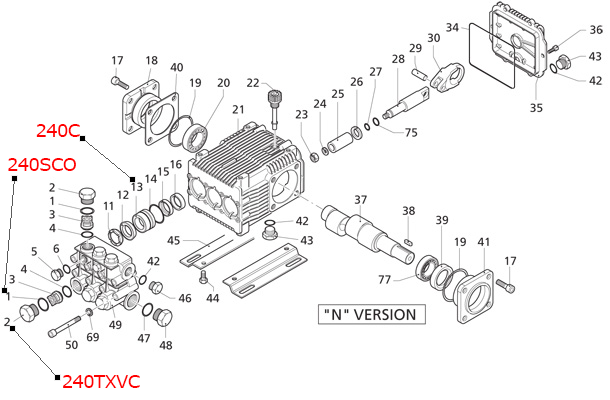
Model 5009 Pump Diagram
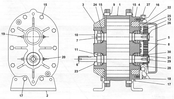
| 1: 850G Housing | 2: Mounting Foot | 3: 850PQ Drive End Plate |
| 4: 850GQ Gear End Plate | 5: Gear Cover | 6: 850DQ Drive Rotor |
| 7: 850DF Driven Rotor | 8: Timing Gear | 9: Dowel Pin |
| 10: 850HP Bearing Cover | 11: 850G Roller Bearing | 12: 850H Bearing |
| 13: 850I Bearing | 15: Screw, Hex Head | 16: Screw, Hex Head |
| 17: Screw, Hex Head | 18: Oil Plug | 19: Relief Fitting |
| 20: Grease Fitting | 22: Bearing Retainer | 23: 850E Lip Seal |
| 24: 850F Lip Seal | 25: Screew, Hex Head | 26: Washer |
| 27: Breather | 28: Spacer | 29: Screw, Hex Head |
| 30: Timing Shims | 31: Gear Timing Key | 42: Alum Nameplate |
| 43: Dr, screew | 47 Teflon Vent Insert |
Model 5006 Pump Diagram
| 1: 850GH Housing | 2: Mounting Foot | 3: 850P Drive End Plate |
| 4: 850GP Gear End Plate | 5: Gear Cover | 6: 850DR Drive Rotor |
| 7: 850DE Driven Rotor | 8: 850TG Timing Gear | 9: Dowel Pin |
| 10: 850HB Bearing Cover | 11: 850G Roller Bearing | 12: 850H Bearing |
| 13: 850I Bearing | 15: Screw, Hex Head | 16: Screw, Hex Head |
| 17: Screw, Hex Head | 18: Oil Plug | 19: Relief Fitting |
| 20: Grease Fitting | 22: Bearing Retainer | 23: 850E Lip Seal |
| 24: 850F Lip Seal | 25: Screew, Hex Head | 26: Washer |
| 27: Breather | 28: Spacer | 29: Screw, Hex Head |
| 30: Timing Shims | 31: Gear Timing Key | 42: Alum Nameplate |
| 43: Dr, screew | 47 Teflon Vent Insert |
Troubleshooting
If using a spray lubricant, exercise care to prevent the applicator tube from getting sucked into the blower. The applicator tube will damage the blnwen most likely to the point that repair would be required.
* 3-in-One and WD-40 are registered trademarks of WD40 Company
Although Competitor blowers are well designed and manufactured, problems may occur due to normal wear and the need for readjustment. The chart below lists symptoms that may occur along with probable causes and remedies.
| Symptom | Probable Cause | Remedies |
| Loss of oil | Gear housing not tightened properly. | Tighten gear housing bolts. |
| Lip seal failure. | Disassemble and replace lip seal. | |
| Insufficient sealant. | Remove gear housing and replace sealant. | |
| Loose drain plug. | Tighten drain plug. | |
| Excessive bearing or gear wear | Improper lubrication. | Correct oil level. Replace dirty oil. |
| Excessive belt tension. | Check belt manufacturer's specifications for tension and adjust accordingly. | |
| Coupling misalignment. | Check carefully, realign if necessary. | |
| Lack of volume | Slipping belts. | Check belt manufacturer's specifications for tension and adjust accordingly. |
| Worn lobe clearances. | Check for proper clearances. | |
| Speed too low. | Increase blower speed within limits. | |
| Obstruction in piping. | Check system to assure an open flow path. | |
| Knocking | Unit out of time. | Re-time. |
| Distortion due to improper mounting or pipe strains. | Check mounting alignment and relieve pipe strains. | |
| Excessive pressure differential. | Reduce to manufacturer's recommended pressure. Examine relief valve and reset if necessary. | |
| Worn gears. | Replace timing gears. | |
| Excessive blower tempurature | Too much or too little oil in gear reservior. | Correct oil level Replace dirty oil. |
| Too low operating speed. | Increase blower speed within limits. | |
| Clogged filter or silencer. | Remove cause of obstruction. | |
| Excessive pressure differential. | Reduce pressure differential across the blower. | |
| Elevated inlet tempurature. | Reduce inlet tempurature. | |
| Worn lobe clearances. | Check for proper clearances. | |
| Rotor end or tip dragging | Insufficient assembled clearances. | Correct clearances. |
| Case or frame distortion. | Check mounting and pipe strain. | |
| Excessive operating pressure. | Reduce inlet tempurature. | |
| Excessive operating tempurature. | Reduce pressure differential or reduce inlet tempurature. | |
| Vibration | Belt or coupling misalignment. | Check carefully, realign if necessary. |
| Lobes rubbing. | Check cylinder for hot spots, then check for lobe contact at these points. | |
| Worn bearings or gears. | Check condition of gears and bearing. Replace if necessary. | |
| Unbalanced or rubbing lobes. |
Possible buildup on casing or lobes, or inside lobes. Remove buildup and restore clearances. |
|
| Driver or blower loose. | Check mounting and tighten if necessary. | |
| Piping resonance. | Check pipe supports, check resonance of nearby equipment, check foundation. |